In a multi-die package, no chiplet is thermally independent. Heat generated in one component travels through shared materials and changes the operating conditions of its neighbors—sometimes immediately enough to shape the package, and sometimes late enough to shape the workload.
Chiplets promise a practical way to combine compute, memory, I/O, analog, and other functions without forcing every block onto one monolithic die. But the package that connects those functions electrically also connects them thermally. A high-power compute chiplet can warm a nearby memory stack, an optical device, or another logic die even when that neighbor dissipates little power of its own.
What thermal coupling means
Thermal coupling is the transfer of thermal influence from one component or region to another through a shared physical path. The path can pass through silicon, microbumps, underfill, an interposer, package substrate, thermal interface material, a lid or heat spreader, a cold plate, or several of these structures in parallel. The affected component does not need to touch the heat source directly. It only needs to share a conductive path and a finite ability to store heat.
For chiplets, the practical question is therefore not simply, “How hot does each die become?” It is, “How much does power in one die change the temperature of every other die, through which paths, and after what delay?” That shift turns thermal analysis from a collection of isolated temperature checks into a system-level interaction problem.
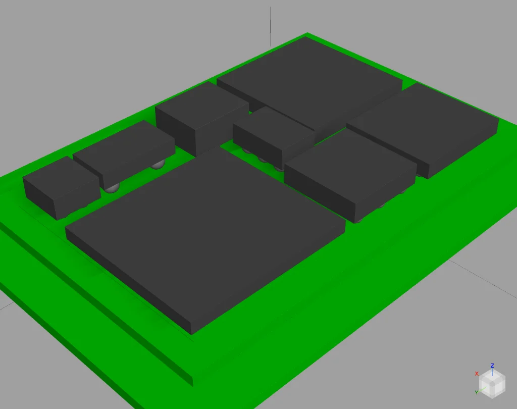
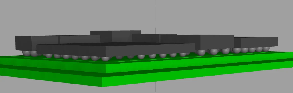
Figure 1. Two views of an illustrative multi-chiplet package. The side view exposes the shared interposer and discrete attachment structures that provide both vertical and lateral heat-transfer paths.
Two aspects of coupling: steady state and time
Steady-state coupling reveals the final influence
A steady-state solution asks what temperatures and heat flows remain after the power distribution and boundary conditions have been held long enough for the system to stop changing. It is useful for identifying the eventual temperature rise imposed on neighboring chiplets, the dominant heat-transfer routes, shared cooling bottlenecks, and regions where heat is forced through a narrow interface.
A simple way to quantify steady coupling is to change the power of one chiplet and measure the resulting temperature change at another. The ratio of neighbor temperature rise to source power has the character of a coupling thermal resistance. Repeating that experiment for every source and receiver produces a thermal interaction map for the package.
Transient coupling reveals the delay
Real workloads do not hold power constant. When one chiplet enters a high-power phase, its own temperature rises first. Heat then propagates through the package, and another chiplet responds later. The strength and timing of that response depend on both thermal resistance and thermal capacitance: materials resist heat flow while their mass stores energy.
That delay matters. A neighbor may reach its peak temperature after the source has already left the high-power phase. Multiple bursts can overlap thermally even when they do not overlap electrically, and a workload can inherit heat left by an earlier workload. Average power alone cannot represent this history.
Useful mental model: Steady-state coupling describes where the package eventually settles. Transient coupling describes the package's thermal memory—the magnitude, delay, and decay of one component's temperature response to another component's power.
Why workloads—and especially AI workloads—matter
Modern AI systems shift activity among compute arrays, local caches, high-bandwidth memory, data-movement engines, and inter-chiplet links. These blocks do not necessarily peak together. A compute-intensive phase may heat a memory device after the memory traffic has subsided; a later memory-bound phase may then begin from an elevated thermal baseline. Burst length, duty cycle, phase ordering, and idle intervals all become thermal design inputs.
A workload-aware thermal model should therefore apply time-varying power to each chiplet and retain the system's thermal state between phases. This enables more realistic prediction of throttling, guard-band violations, cooling demand, and the value of scheduling or power-management decisions. It also exposes a key design opportunity: architecture, packaging, cooling, and workload control can be optimized together rather than sequentially.
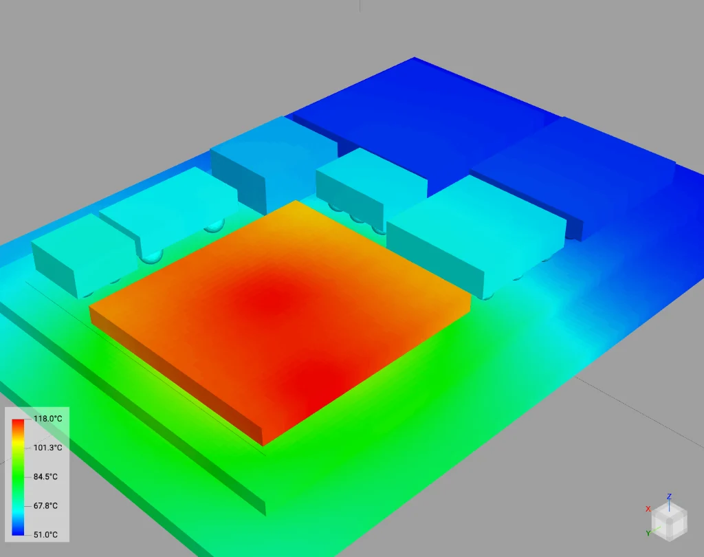
Figure 2. Illustrative steady-state temperature solution for the package in Figure 1. The displayed range is approximately 51–118 °C. Temperatures depend on the assumed powers, materials, interfaces, and boundary conditions; the figure is used here to show spatial thermal influence rather than validate a specific product.
Reading a steady-state coupling path
Temperature contours show the result of coupling, but heat-flux vectors reveal the route. In this illustrative case, heat leaves the powered source, crosses its attachment interfaces, spreads laterally through the interposer, and enters neighboring chiplets through their own attachment regions. The path is three-dimensional and nonuniform: discrete bumps, material transitions, and geometry concentrate or redirect the flow.
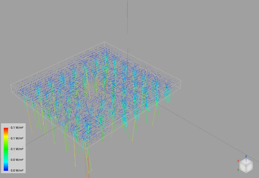
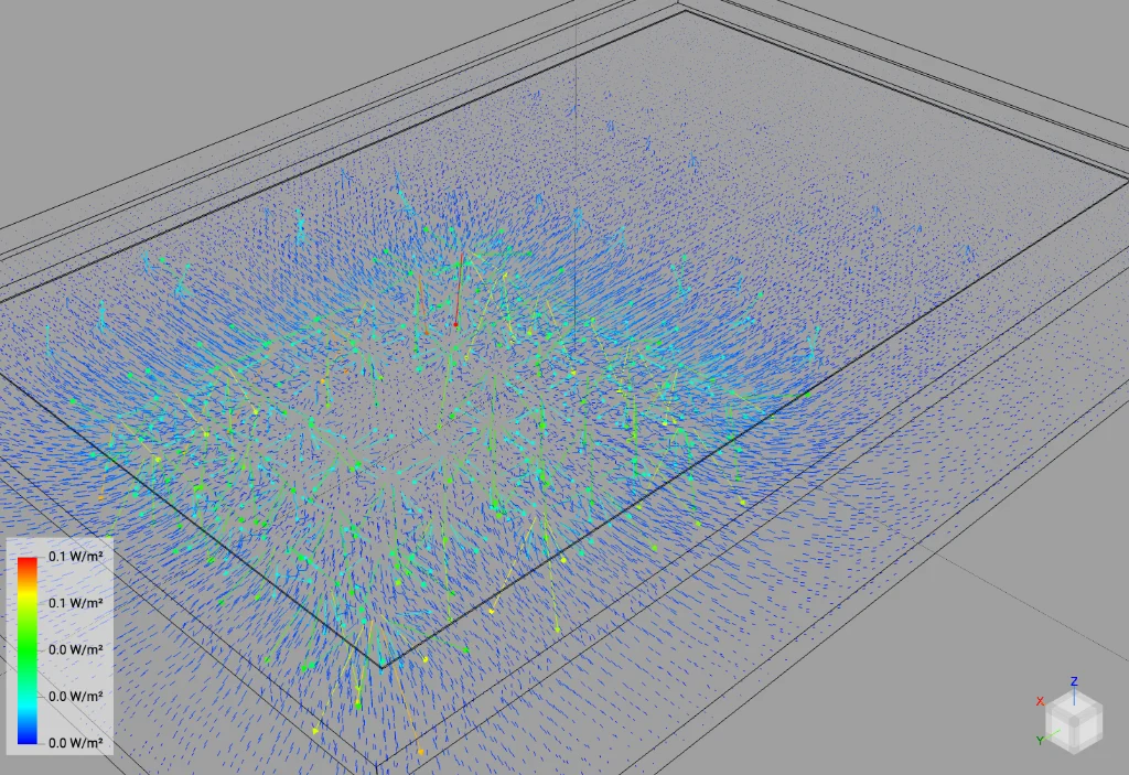
Figure 3. Steady heat flux leaving the source chiplet (left) and spreading laterally through the interposer (right). Direction and spatial distribution are the important information here; the displayed magnitude scales are rounded.
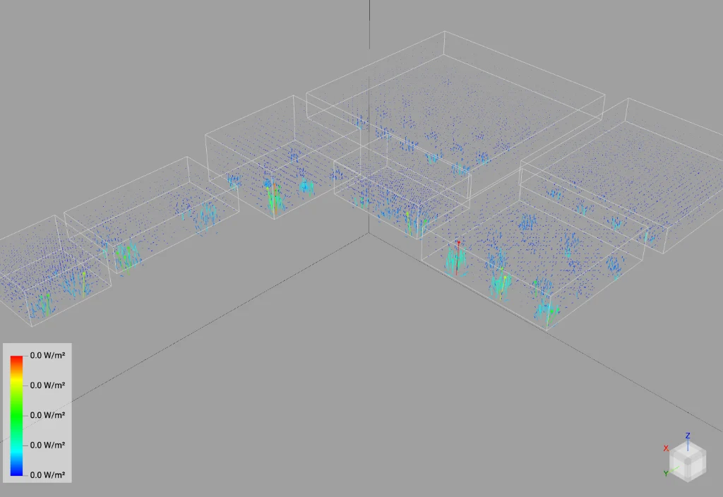
Figure 4. Steady heat flux entering neighboring chiplets. Coupling is localized around attachment and interface regions rather than being uniform across each die.
Two ways to reshape the path
Once the dominant coupling path is visible, the package can be modified rather than treated as a fixed thermal environment. Two broad strategies are especially useful.
1. Break, intercept, or shunt the path
A thermal structure can be placed so that heat is spread or removed before it reaches a sensitive neighbor. Depending on the package, this may involve a high-conductivity bridge to a cooler region, a local heat spreader, a thermal via field, a dedicated lid feature, or a direct path into a cold plate. The important distinction is that the added structure must provide a better destination for the heat; merely adding conductive material can strengthen coupling if it connects the source more effectively to the neighbor.
2. Make the thermal coupling path longer
Increasing separation or forcing heat to follow a less direct route raises the effective coupling resistance and often increases the propagation delay. The neighbor then experiences a smaller or later temperature rise. The tradeoff is that the source can become hotter if no alternative removal path is improved. Distance is therefore not a complete cooling strategy; it is a coupling-control strategy that must be evaluated with the source temperature and total package size.
A familiar package-level example: Apple M1
Apple described the M1 as its first system on a chip for the Mac and highlighted a unified memory architecture in which high-bandwidth, low-latency memory forms a single pool within a custom package.[1] The M1 was not the first processor package ever to include DRAM, but it made close package-level integration of a powerful personal-computing SoC and low-power memory highly visible.
That integration creates a thermal co-design problem. Logic and LPDDR have different power densities, activity patterns, temperature sensitivities, and performance constraints. Placing the memory beside the SoC rather than directly over its hottest region makes the coupling path longer, while the shared package and cooling environment preserve a finite thermal connection.

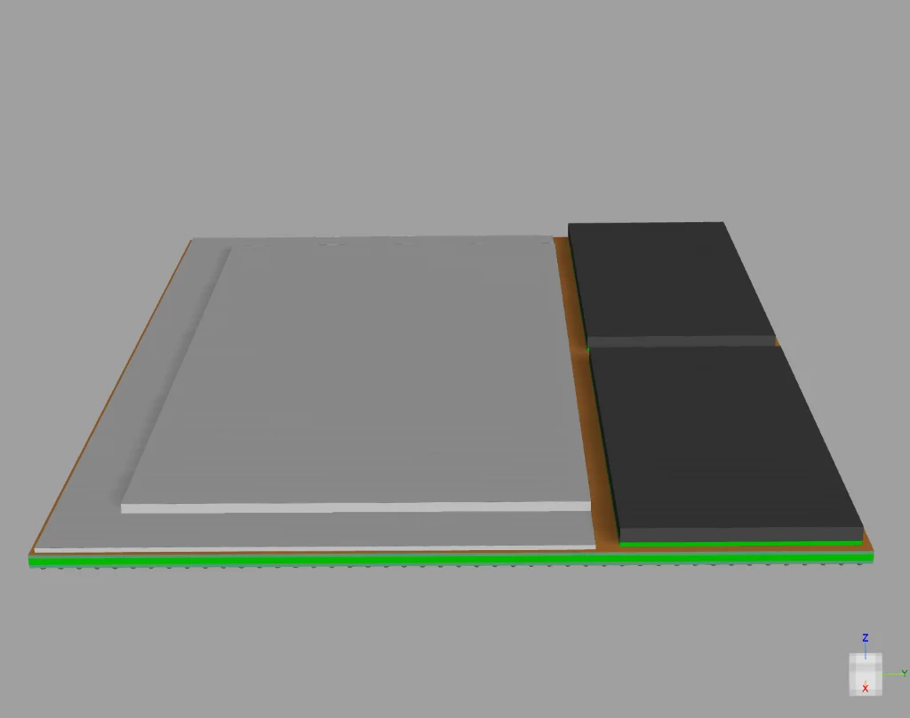
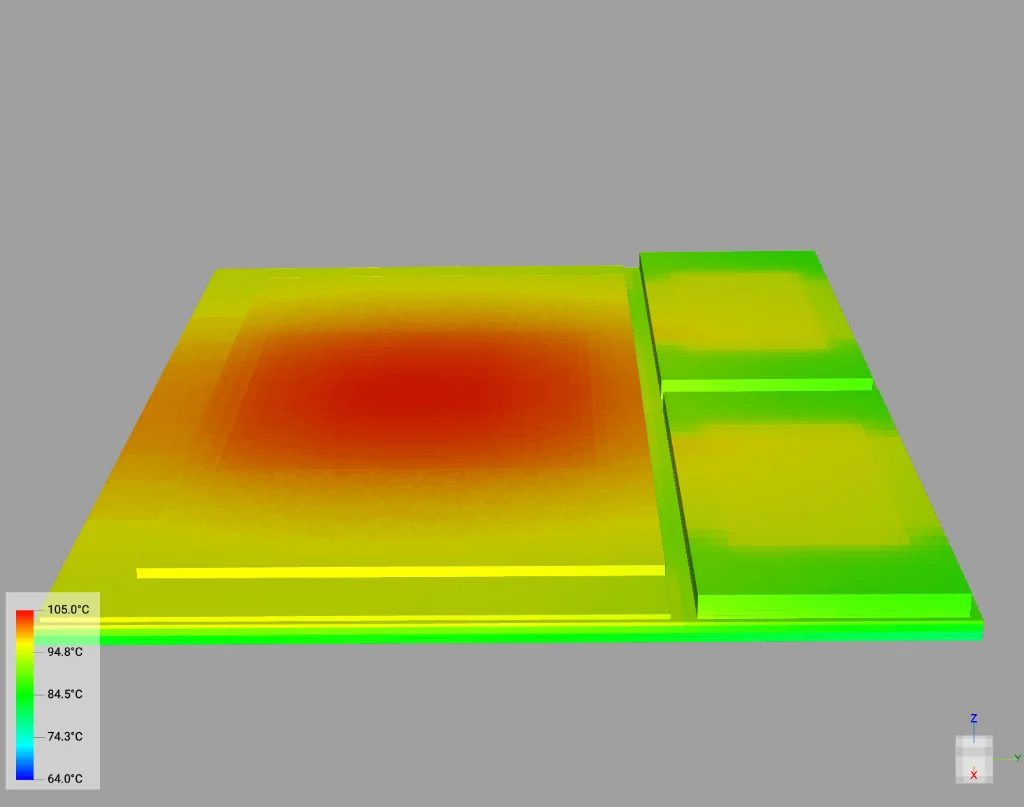
Figure 5. Simplified illustrative M1 package model (left) and steady-state temperature solution (right). The simulated range is approximately 64–105 °C. This is not an Apple-validated geometry or thermal result.
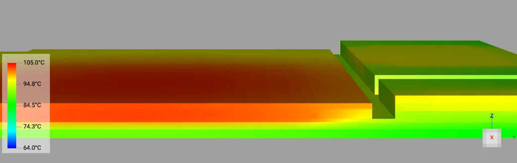
Figure 6. Cross-section of the illustrative temperature distribution between the SoC and LPDDR packages. The continuous gradient shows that separation reduces but does not eliminate package-level coupling.
Denser integration needs engineered thermal paths
As inter-chiplet spacing shrinks and 2.5D and 3D integration become more aggressive, designers lose the freedom to solve coupling by distance alone. Future packages will need structures that deliberately shape the thermal network. Some structures can draw heat toward a sink; others can block or divert a dominant lateral path. Which approach works depends on where the strongest path actually resides.
A 2025 study by George Karfakis and colleagues at UCLA and Georgia Tech, including Puneet Gupta, examined embedded thermal isolators inside the heat spreader of a water-cooled 2.5D GPU-and-HBM system.[2] The paper reports that the heat spreader can dominate chiplet-to-chiplet coupling, limiting the value of floorplanning alone. In the evaluated simulations, engineered isolators increased thermal isolation by as much as 61%; selected configurations also reduced average peak chip temperature by as much as 22.5% and improved memory-bound workload performance by up to 37% through reduced thermal throttling.
The broader lesson is not that every package needs an isolator. It is that the coupling path must be found before it can be modified. If heat primarily couples through the interposer, a lid-only change may miss the problem. If a shared heat spreader dominates, moving chiplets apart on the interposer may consume area without delivering the expected isolation.
Design the thermal network, not isolated temperatures
Thermal coupling is becoming a first-order architectural constraint for chiplet systems. Steady-state analysis identifies the eventual influence and the paths that carry it. Transient analysis captures delay, overlap, and thermal history under realistic workloads. Heat-flux inspection shows where an intervention can work, while workload-aware simulation reveals when it must work.
The most useful design question is therefore not, “What is the maximum temperature?” It is, “Which component heated which neighbor, through what path, on what time scale, and what can we change?” Once coupling is treated as a designed network, package geometry, materials, cooling, architecture, and workload management become parts of the same engineering problem.
How Anemoi Software helps
This is the exact problem DankaThermal™ is built to model — steady-state and transient coupling, workload-aware power phases, and heat-flux paths through the real package stack, not just isolated temperature checks. Teams use it to find the dominant coupling path before committing to a floorplan or heat-spreader design.
Related reading: Thermals for Chiplets: Managing Heat in Heterogeneous Integration and Why 2.5D Systems Need Thermal Isolation, Not Just Better Floorplanning — the isolator study referenced above is covered in more depth there.
Want to see this kind of coupling analysis on your own package? Talk to Anemoi Software.
Sources
1. Apple, “Apple unleashes M1,” November 10, 2020.
2. G. Karfakis, M. Bouzidi, Y. Im, A. Graening, S. K. Sitaraman, and P. Gupta, “Optimizing Thermal Performance in 2.5D Systems Using Embedded Isolators,” IEEE Journal on Emerging and Selected Topics in Circuits and Systems, 2025. DOI: 10.1109/JETCAS.2025.3595909. Open paper: https://nanocad.ee.ucla.edu/wp-content/papercite-data/pdf/j84.pdf